
UML Sequence Diagram - Custom is one of the interactive graphs Understand can draw of your code — call trees, dependencies, control flow, and more.
UML Sequence Diagram - Custom
Languages: AnyTargets: Functions
A plugin version of the UML Sequence Diagram
The UML Sequence Diagram in Understand is drawn with a custom layout algorithm, not Graphviz. This graph demonstrates how to use the otherwise undocumented layout algorithm. It can be used as a basis for customizing the UML Sequence Diagram.
UML Sequence Diagram Layout
Consider a simple UML Sequence Diagram that just contains a single activation:
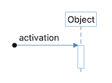
The black circle on the left is the "Found Message", the beginning of the graph. It connects to an activation box for the initial function. The function belongs to the object "Object". Representing this graph in a simplified Graphviz dot format would be something like this
    digraph "name" {
      foundmessage -> activation [label="activation"];
      object -> activation;
    }
The problem for the layout algorithm is how to know which node is the found message, drawn directly to the left of the activation node, and which node is the object node, drawn directly above it. Because the model generation code and the layout code where initially combined, the layout relies on the model to say where the items are. Specifically, the attributes "row" and "col" are nearly always required.
The following image shows where the rows and columns are. Note that row and column are not final positions. They just place all the objects onto a grid. Also, not all objects are necessarily drawn. Rows 4 and 9 are defined by return edges that are not visible in the final graph. Row 8 isn't defined at all, but it's absence signals the end of the cluster.
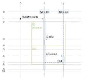
There are three other attributes unique to the layout to be aware of:
- uml This is required for every node, edge, and cluster. It is similar to the Graphviz "shape" attribute and determines how objects are drawn.
- nesting This is required on every activation node. It's used to indent self calls.
- visible This is required on every return edge. Every activation node has to have a return edge, used to define the end row of the activation box. Since return edges should not always be drawn, the "visible" attribute controls visibility.
In addition to the than the five attributes described above ("row", "col", "uml", "nesting" and "visible"), the layout supports a few Graphviz attributes. They are:
- color the line color
- fillcolor the fill color
- fontcolor the font color
- style specifically line styles, like "dashed"
- width spacer items only, required
- height spacer items only, required
A list of possible "uml" values are below. Note that unlike the Graphviz shape attribute, values of "uml" cannot appear just anywhere. The layout algorithm will not work if items do not appear as expected. The possible values of "uml" are:
- Nodes:
- object the objects in row 0
- foundmessage the initial point, the only item in column 0
- activation activation boxes drawn along an object's lifeline
- spacer the final row of the diagram, used as an end point for lifelines
- Edges:
- message an edge from left to right, beginning an activation node
- return an edge from right to left, ending an activation node
- lifeline a vertical edge, showing an object's lifeline
- Clusters:
- combinedfragment the bounding box of an entire cluster. The label is "alt" or "loop".
- section the area within a combined fragment. Every combined fragment must have at least one section. Section labels are usually the condition for the loop or alt.
This variant is a plugin. It can be enabled/disabled from the Plugin Manager.